Download OS CAD Maps

Start with your address

Search your address to preview the CAD export area

Licensed CAD area · 3 ha (173m × 173m)

Before you order

Know what is in your CAD download

What will I receive?
DWG and DXF linework in OSGB36 British National Grid coordinates, supplied in metres. Optional contours are a separate selection.
Is it right for my application?
A base for architectural and planning drawings. OS mapping is not a measured site survey and does not establish legal ownership boundaries.
Which scale and coverage?
Select the mapped area in hectares. CAD uses real coordinates; choose the plotting scale in your drawing software. Check the coverage before paying.
Why PlanningMapsUK?
We are an Ordnance Survey Licensed Partner. Preview your map before payment, read customer feedback below, and check our corrections promise for faults attributable to our map output.
What does it cost, and when is it ready?
CAD files from £14.95. Your selected coverage, format and any extras determine the total shown in the builder. Standard digital orders are available to download after payment and generation; printed copies take longer.

Check our OS partner profileRead our map corrections promise

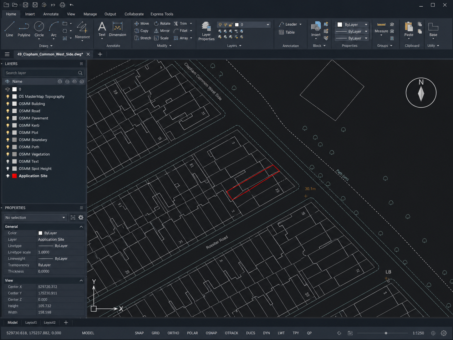
Illustrative CAD software view showing mapping linework and layersView the CAD illustration ↗

OS CAD maps UK

Editable OS mapping for CAD and planning workflows

PlanningMapsUK generates licensed Ordnance Survey CAD map extracts as georeferenced DWG and DXF linework. They are designed for architects, planning consultants, surveyors and development teams that need an editable mapping base instead of a fixed PDF.

Choose the site, scale and coverage online, preview the area and order the files without waiting for a manual quotation. The map is positioned in OSGB36 British National Grid coordinates and supplied in metres.

DWG-specific guide

Built around your work

CAD plans for architects, surveyors and engineers

From an initial site appraisal to a coordinated drawing set, an editable base map helps your team place a proposal in its surroundings. Choose the coverage your project needs, then build on the mapping in your own CAD workflow.

CAD plans for architects

Start extension, infill and new-build studies with the site in context. OS CAD linework gives you mapped building footprints and surrounding streets to reference while developing your own proposed layout.

  • Explore how a proposal sits alongside neighbouring buildings.
  • Prepare context drawings for client discussions and design reviews.
  • Keep base mapping on separate layers from proposed works.

Add your own design information, dimensions and sheet layout to turn the base map into a project drawing.
CAD maps for land and building surveyors

Use an OS mapping extract to plan survey coverage and show the area around your measured work. A wider base map helps explain where the survey sits within the street, site or surrounding land.

  • Plan the extent of a survey before visiting the site.
  • Reference measured survey drawings against wider mapped context.
  • Show surrounding roads and building footprints beyond the survey area.

Keep measured observations distinguishable from OS mapping and confirm coordinate alignment before combining datasets.

CAD base maps for civil engineers

Give early engineering studies a shared site reference. Editable mapping helps teams discuss access, surrounding development and the relationship between proposed works and existing mapped features.

  • Prepare background drawings for feasibility and access studies.
  • Coordinate concept layouts with architectural and survey information.
  • Include enough surrounding context for multidisciplinary reviews.

Detailed engineering needs project-specific survey and investigation data. Base mapping does not establish utility positions or construction levels.

CAD mapping for landscape and planning teams

Set landscape proposals and development options within the wider site. Use mapped paths, buildings and land features as context for your own planting layouts, access routes and appraisal drawings.

  • Compare alternative site layouts on a consistent mapping base.
  • Present the relationship between development and surrounding land.
  • Add optional contours when broader terrain context is useful.

Mapped vegetation is contextual information; use a site-specific tree survey when individual tree measurements or condition are required.

Working in an architectural practice? Explore our guide to CAD maps for architects for more on drawing preparation and design coordination.

Editable lineworkNamed CAD layers
CAD drawing showing mapped buildings and roads, a highlighted site and a named layers panel
Example CAD workspace. Your map provides the surrounding context; add your own site outline, proposals and drawing annotations.

From base map to drawing

Bring your site into the wider picture

A useful CAD extract extends beyond the building itself. Include neighbouring properties, the approach road and any wider context you need to explain the proposal.

  1. 1

    Check units and coordinates

    The supplied mapping uses metres and OSGB36 British National Grid coordinates. Confirm your drawing settings and the coordinate system of any survey before overlaying them.

  2. 2

    Organise the drawing layers

    Use the named feature layers to control visibility and styling. Keep proposed work and annotations separate so the original map remains easy to reference.

  3. 3

    Prepare the output for its purpose

    Set the paper size and viewport scale when preparing a sheet. Check that the selected map coverage, labels and project information are suitable for the intended review or submission.

Need a finished PDF instead? Choose a site location plan or block plan for a fixed-scale sheet.

DWG vs DXF vs PDF maps

The right format depends on what happens after the map is delivered.

FormatBest forEditableGeoreferencedTypical next step
DWGAutoCAD-led architecture and engineering workflowsYesYesAdd design, dimensions and drawing sheets
DXFExchanging drawing data between CAD applicationsYesYesImport into the receiving software and check units
PDFFixed-scale review and planning-submission sheetsLimitedNoUpload or print at the stated paper size

What is included in an OS CAD map?

Standard linework is generated from OS MasterMap Topography data. It can include mapped building footprints, roads, paths, structures, land-form features, walls, fences, vegetation features and cartographic text for the selected area.

  • Buildings and structures: detailed mapped footprints for the site and surrounding context.
  • Roads and paths: carriageway, footway and route linework relevant to access and layout work.
  • Physical features: mapped walls, fences, vegetation and other topographic detail where present in the source.
  • Optional contours: OS Terrain 5 contour linework can be added when terrain context is needed.

OS topographic linework is not a legal property-boundary record and does not replace a measured topographical survey. Check the map against current site conditions and use the appropriate specialist data for title, level or construction decisions.

Common CAD map scales and prices

These current options show how scale and coverage affect the order.

ScaleCoverageFromTypical use
1:2000.1ha£14.95Detailed compact site
1:5000.81ha£29.95Block plan or site layout
1:12503ha£59.95Wider planning context
1:250020ha£235.95Large or rural sites

Larger coverage tiers are available. Prices shown are for the stated entry option and may change when extra layers are selected.

Four-step workflow

How to download an OS CAD map

  1. 01

    Find the site

    Search the address or postcode and confirm the correct map position.

  2. 02

    Choose coverage

    Select the scale and area that includes every feature needed by the design team.

  3. 03

    Check options

    Review DWG and DXF delivery and add contours or other available data only when required.

  4. 04

    Download the files

    Complete checkout, follow the order status and open the delivered CAD files in your chosen software.

OS CAD map FAQs

How do architects use CAD base maps?

Architects can use an editable CAD base to explore site layouts, show neighbouring buildings and prepare context drawings. Keep proposed works on separate layers and add the project information needed for each drawing. For a more detailed workflow, see our CAD maps for architects guide.

Can I combine an OS CAD map with a measured survey?

Yes, as contextual mapping, provided you check the units and coordinate systems first. Our CAD maps use metres and OSGB36 British National Grid coordinates. A survey on a local grid needs appropriate alignment before overlaying it. Keep the survey and OS mapping distinguishable so their different sources are clear.

How much surrounding area should I include in my CAD plan?

Include the site and the surrounding features needed to explain your proposal, such as neighbouring buildings and the approach road. Check the preview against the drawing brief before ordering. A compact extension study and a wider development appraisal may need different coverage, even if they concern the same address.

What is an OS CAD map?

An OS CAD map is editable linework generated from licensed Ordnance Survey mapping and supplied for use in computer-aided design software. PlanningMapsUK delivers DWG and DXF files positioned in OSGB36 British National Grid coordinates.

What is the difference between DWG and DXF?

DWG is AutoCAD's native drawing format. DXF is a drawing interchange format used to transfer drawing information between CAD applications. PlanningMapsUK supplies both formats with the same mapped area.

Can I use an OS CAD map as a topographical survey?

No. OS MasterMap provides detailed topographic mapping, but it is not a site-specific measured survey. Use a professional topographical survey when design or construction depends on precise levels, drainage, structures or setting-out dimensions.

Do CAD maps show legal property boundaries?

No. Mapped walls, fences and other physical features are topographic detail and should not be treated as legal ownership boundaries. Use the appropriate Land Registry documents or boundary data when title extent matters.

Are the DWG and DXF files georeferenced?

Yes. The CAD linework is positioned in OSGB36 British National Grid coordinates and supplied in metres. Check the receiving drawing units and coordinate settings when importing it into another project.

Can I add contours to my CAD map?

Yes. OS Terrain 5 contours are available as an optional separate layer for projects that need terrain context. They are not included automatically in the standard MasterMap linework.