
When embarking on a home improvement project, people frequently use the word "plans" as a catch-all term for everything submitted to the council. That casual wording often leads to expensive delays. An applicant is told they need "plans for planning permission", hears terms like location plan, block plan, floor plans, and elevations, and assumes they can all be purchased as ready-made documents from a single website.
In reality, a complete planning submission brings together three distinct categories of work: statutory mapping, architectural design drawings, and supporting technical statements. Conflating these categories leads property owners to pay architects to re-create maps that could have been ordered in minutes, or to submit unscaled sketches that are immediately rejected at council validation.
This guide clarifies each document type, who prepares it, and the order in which you should assemble your pack. For the wider setting, choose a site location plan. For detailed site mapping, create a site plan or choose the block-plan option. If an architect needs editable mapping, choose CAD mapping; the comparison table below links to the files. Our OS planning maps guide helps you compare the options; floor plans, elevations and proposed layouts are separate drawings.

Need plans for planning permission?
What Plans Do You Actually Need for Planning Permission?
A standard planning application submitted via the Planning Portal contains three distinct categories of material:
- Statutory Planning Maps: Official, scaled geographic plans based on licensed Ordnance Survey MasterMap data showing the property's legal boundaries and street access.
- Architectural Design Drawings: Detailed drawings showing the exact dimensions, internal layouts, and exterior appearance of the proposed building works.
- Supporting Statements & Reports: Written documentation addressing specific planning constraints such as conservation areas, tree preservation, flood risks, or structural engineering.
At-a-Glance: Planning Maps vs Architectural Drawings
| Document Name | Document Category | Typical Metric Scale | Primary Purpose | Who Prepares It |
|---|---|---|---|---|
| Site Location Plan | Statutory Planning Map | 1:1250 or 1:2500 | Identifies the application site and its surrounding road context | Licensed OS map provider |
| Block Plan / Site Plan | Statutory Planning Map | 1:500 or 1:200 | Shows building footprints, garden boundaries, and setbacks | Licensed OS map provider |
| OS CAD Vector Map | Digital Mapping Asset | 1:1 real-world vector | Layered DWG/DXF geometry imported into AutoCAD/Revit | Licensed OS map provider |
| Existing & Proposed Floor Plans | Architectural Drawing | 1:50 or 1:100 | Illustrate internal room layouts, wall positions, and room uses | Architect / Designer |
| Existing & Proposed Elevations | Architectural Drawing | 1:50 or 1:100 | Illustrate external facades, materials, window styles, and heights | Architect / Designer |
| Roof Plans & Cross-Sections | Architectural Drawing | 1:50 or 1:100 | Detail roof profiles, dormer cheeks, pitch angles, and ridge heights | Architect / Designer |
| Design & Access Statement | Supporting Document | N/A (written report) | Explains design concept, access principles, and planning policy fit | Planning consultant / Architect |
Category 1: Statutory Planning Maps (Order First)
Planning maps form the legal foundation of your entire submission. You should order these first so that all subsequent design drawings align to the exact boundary coordinates:
The Site Location Plan (1:1250)
- Role: Identifies the property within the local road network and council GIS records.
- Key Features: True North arrow, graphic metric scale bar, OS Crown copyright licence, and a continuous red line enclosing the plot and driveway out to the public adopted highway.
The Block Plan (1:500)
- Role: Zooms in on the immediate property curtilage to illustrate proposed building footprints relative to boundary fences and neighbouring dwellings.
- Key Features: Boundary clearances, tree positions, parking arrangements, and metric dimensions.
CAD Vector Mapping (DWG / DXF)
- Role: Provides your architect or structural designer with layered Ordnance Survey vector coordinates. This eliminates manual tracing and prevents drafting inaccuracies.
Category 2: Architectural Drawings (Prepared by Your Designer)
Once your licensed base mapping is secured, your architect or designer drafts the architectural design drawings:
Floor Plans (Existing and Proposed)
Drawn at 1:50 or 1:100 scale, floor plans represent a horizontal slice through the building. They detail internal room layouts, door swings, window openings, and wall thicknesses, clearly contrasting existing arrangements with proposed alterations.
Elevations (Existing and Proposed)
Drawn at 1:50 or 1:100 scale, elevations show external facades viewed straight-on from the north, south, east, and west. They detail exterior finishes (e.g. brickwork, render, slate tiles), window frames, gutter lines, and overall ridge heights.
Roof Plans and Sections
Essential for loft conversions, dormers, and complex extensions to prove that roof heights and pitch angles blend harmoniously with neighbouring rooflines.
Architectural Drawing Conventions: What Planners Expect to See
Planning officers inspect dozens of drawing sets every week. Adhering to standard UK architectural drawing conventions ensures your submission is instantly understood:
- Lineweights and Contrast:
- Existing Building Elements: Drawn with medium or light grey lines (0.18mm to 0.25mm) so they recede into the background.
- Proposed New Construction: Emphasized with bold linework (0.35mm to 0.50mm) and solid hatching or color tinting.
- Demolished Structures: Highlighted with yellow shading or dashed red lines, accompanied by a clear key: "Walls shown dashed to be demolished".
- The Street Scene Elevation: On two-storey side extensions or new dwellings, planning officers frequently require a 1:100 or 1:200 Street Scene drawing. This drawing illustrates your proposed facade flanked by the immediate houses on either side, demonstrating that your new roof ridge sits subserviently below the main roofline and respects suburban rhythm.
- Finished Materials Annotations: Every proposed elevation must explicitly list external materials to satisfy planning officers and conservation teams: e.g. "Roof: Natural Welsh slate to match existing dwelling. Walls: Red facing brickwork in Flemish bond with mortar colour to match host property. Windows: White timber-framed double-glazed sashes."
Planning Drawings vs Building Regulations Drawings
A frequent error made by property owners is assuming that planning drawings can be reused directly for building construction. In reality, Planning and Building Regulations are governed by entirely separate legislation:
| Aspect | Planning Permission Drawings | Building Regulations Drawings |
|---|---|---|
| Statutory Purpose | Evaluates external appearance, neighborhood character, amenity, and land use under the Town and Country Planning Act 1990. | Evaluates structural integrity, life safety, fire escape, energy efficiency, and accessibility under the Building Act 1984. |
| Typical Scale | 1:50 or 1:100 elevations and floor plans; 1:500 block plan; 1:1250 location plan. | 1:20 and 1:10 construction details; 1:50 structural general arrangements; engineering calculation sheets. |
| Level of Detail | Shows external walls, window openings, ridge heights, and materials. Omits internal joist sizes, foundation depth, and steel specifications. | Exhaustive technical specification: beam calculations, insulation U-values, radon membranes, drainage falls, and fire doors. |
| Why Keep Them Separate? | Submitting full construction drawings to planning causes confusion, clutters public registers, and risks unnecessary planning conditions tied to minor internal details. | Building control bodies need complete engineering proof before approving building work on site. |
Drawing Numbering and Revision Control
Planning applications often undergo minor design tweaks during negotiations with the case officer. Adopting professional version control prevents disastrous misunderstandings:
- Standard Drawing Title Block: Positioned at the bottom-right corner of every sheet, displaying the project address, applicant name, drawing title (e.g. "Proposed Ground Floor Plan"), scale ratio, paper size, and date.
- Sequential Drawing Numbers: Use a logical numbering hierarchy:
PL-01: Site Location Plan (1:1250)PL-02: Block Plan / Site Plan (1:500)PL-03: Existing Floor Plans & Elevations (1:100)PL-04: Proposed Ground & First Floor Plans (1:50)PL-05: Proposed Elevations & Sections (1:100)
- Revision Suffixes: If you reduce the extension depth by 0.5 metres following a neighbour consultation objection, re-label the sheet from
PL-04toPL-04 Rev A. Always include a revision revision note in the title block: "Rev A: Extension depth reduced by 500mm to address daylight query (Dated: 12/05/2026)".
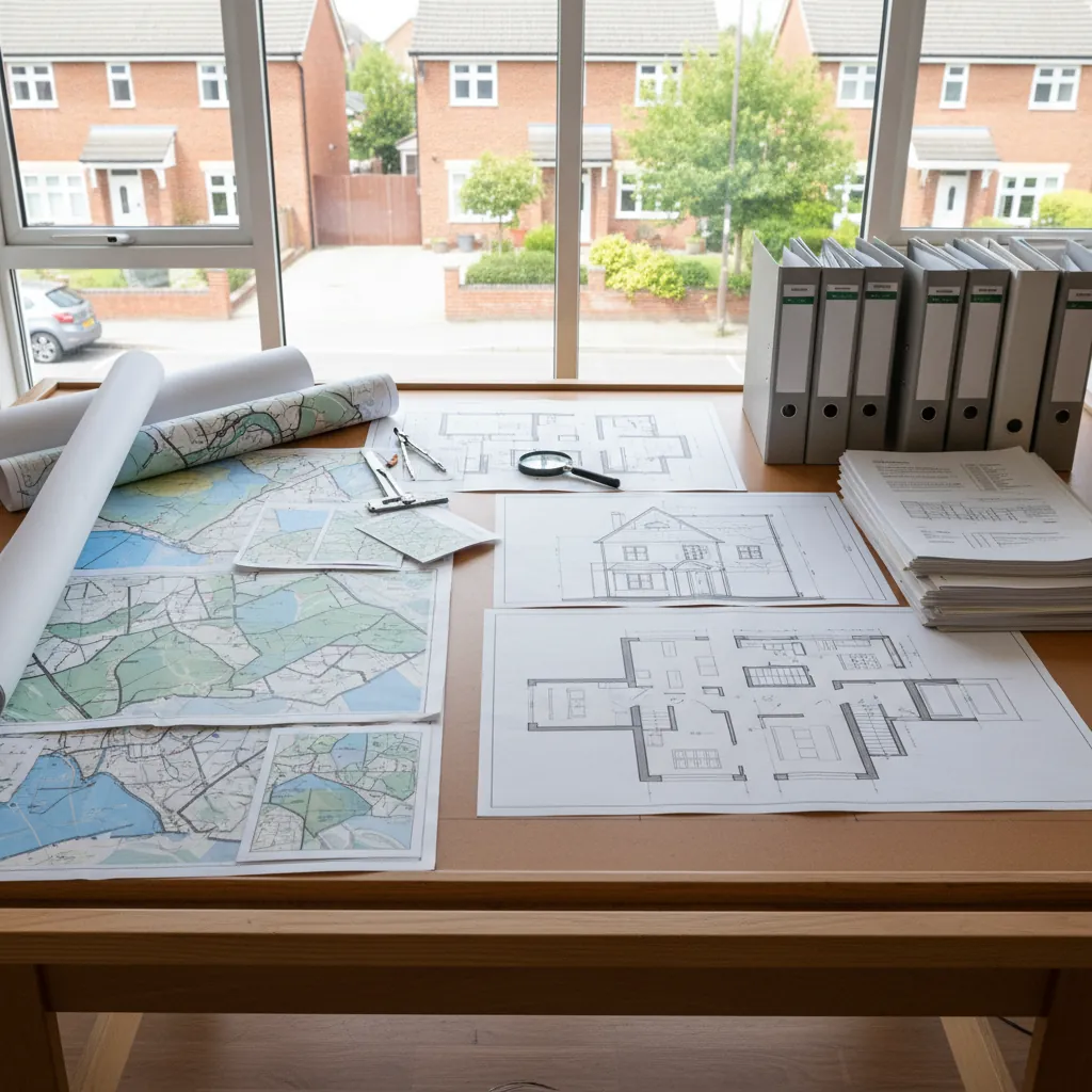
At-a-glance table: maps vs drawings vs supporting documents.
Category 3: Supporting Technical Reports
Depending on your site constraints, the local planning authority may request specialized documentation:
- Heritage Statement: Required if your building is listed or situated within a Conservation Area.
- Tree Survey (BS 5837): Required if mature trees sit within 15 metres of proposed excavations.
- Flood Risk Assessment (FRA): Mandatory if your site sits within Environment Agency Flood Zone 2 or 3.
- Ecology / Bat Survey: Triggered when altering older roof structures where protected species may roost.
The Recommended Assembly Sequence
To avoid wasted expenditure and drawing revisions, assemble your planning application in this order:
- Order Statutory Planning Maps: Secure your 1:1250 location plan and 1:500 block plan.
- Confirm CAD Requirements: Check whether your architect requires editable DWG/DXF files before they commence drafting.
- Draft Architectural Drawings: Have your designer produce scaled existing and proposed floor plans and elevations based on the OS linework.
- Commission Technical Reports: Only order specialist surveys (tree, flood, heritage) if your local authority validation checklist explicitly triggers them.
- Upload to Planning Portal: Upload all documents into their dedicated slots with correct descriptive labels.
Frequently Asked Questions
What plans are legally required for UK planning permission?
A standard application requires statutory planning maps (a 1:1250 site location plan and a 1:500 block plan), architectural design drawings (existing and proposed floor plans and elevations at 1:50 or 1:100), and any required supporting technical statements.
Is a site location plan the same as a floor plan?
No. A site location plan is a statutory geographic map showing the property within the local road network. A floor plan is an internal architectural drawing showing room dimensions, door openings, and interior partitions.
Do I need both a location plan and a block plan?
Yes, for all applications that involve physical construction, extensions, outbuildings, or changes to highway access. The location plan identifies the legal plot, while the block plan illustrates building clearances and garden boundaries.
Who prepares the architectural drawings for planning permission?
Architectural drawings (floor plans, elevations, sections) are typically drawn by an architect, architectural technologist, or draughtsperson. Statutory planning maps are supplied by licensed Ordnance Survey mapping providers like PlanningMapsUK.
When do I need vector CAD files instead of PDF plans?
You need CAD mapping (DWG or DXF formats) when your architect or structural engineer requires raw vector lines to import into CAD software, rather than tracing over a static PDF.
Can I draw my own plans for planning permission?
Yes, provided they meet national validation criteria, use identified metric scales (e.g. 1:100 for floor plans, 1:500 for block plans), include metric scale bars, and clearly show existing versus proposed layouts.
Summary
Navigating planning application requirements is straightforward once you separate the document types:
- Planning Maps: Order your official 1:1250 site location plan and 1:500 block plan first to define your statutory site boundaries.
- Architectural Drawings: Commission your designer to produce scaled floor plans and elevations at 1:50 or 1:100.
- CAD Vectors: Supply your architect with DWG base mapping if they are drafting in AutoCAD or Revit.
Order your official Ordnance Survey planning maps on PlanningMapsUK today with instant PDF download.